

Introduction
With the development of national economy and the improvement of people's living standard, central air conditioning system has been widely used in hotels, hotels, office buildings, shopping malls, hospital buildings, industrial plants and other occasions. Its system structure consists of refrigeration compressor unit, cooling (heating) medium circulating water system, cooling circulating water system, cooling tower fan system, coil fan system, etc. The design capacity of the system is mostly selected according to the maximum cooling, heating load or fresh air exchange demand of the building, with a large margin. In the use process, it is impossible to adjust the number of people with the change of seasons, days and nights. The motor operates at full speed at power frequency for a long time, and the phenomenon of "big horse pulling small car" appears. Although the system adopts gate valve, baffle plate and other throttling methods, the energy waste is still very serious. The power consumption accounts for more than 60% of the total power consumption of the building. Among them, the power consumption of the water pump accounts for about 40% of the total power consumption of the air conditioning system, so there is a large space for energy conservation. Therefore, it is of great economic significance to save the power consumption of main compressor system, water pump and fan system at low load.
Working principle and structure of central air conditioning system
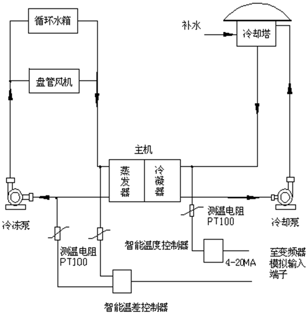
The central air conditioning system is composed of three parts: main unit, chilled water circulation system and cooling water circulation. The control schematic diagram of the cooling water pump is as follows:
According to the load type, the central air conditioning system can be divided into two categories:
◆Constant torque load: such as the compressor of screw or centrifugal refrigeration main compressor system not only has the demand of minimum output torque of shaft, but also the relationship between speed and power is approximately linear.
◆Square torque load: such as cooling circulating water system, refrigerant circulating water system (heat pump circulating water system), cooling tower fan system, coil fan system and other fan and water pump loads, they have no strict demand for shaft torque, and their shaft power and speed have a significant cubic relationship. Different load types have different torque and power relationship characteristics, and the energy saving space is different.
lEnergy saving regulation principle of refrigeration compressor
Take the vapor compression refrigeration cycle as an example, the refrigeration cycle process of the refrigeration system of central air conditioning is shown in the figure above. The power of screw compressor can be adjusted by frequency conversion to reduce the screw speed. (in order to prevent the backflow of high pressure gas from the exhaust end to the exhaust hole, such as fuel injection, the minimum exhaust volume is usually limited to about 10%). Therefore, the power output of screw compressor can be adjusted in the range of 10% - 100%. Empirical data show that when the load of screw compressor is more than 50%, its power is linearly proportional to the load, when the load is less than 40%, the actual power consumption is far greater than the linear theoretical calculation power, therefore the ideal energy-saving effect can not be obtained in the full load range when using the frequency conversion technology, so that the application of the frequency conversion control technology is troubled. It can be seen from the above analysis that for the refrigeration compressor of central air conditioning, the compressor itself has also adopted the automatic regulation mode, so it is generally not recommended to carry out energy-saving transformation for the refrigeration compressor.
lEnergy saving regulation principle of fan and water pump
According to the theory of fluid mechanics, the output flow Q of centrifugal fluid transmission equipment (such as centrifugal pump, fan, etc.) is directly proportional to its rotational speed n; The output pressure P (head) is directly proportional to the square of the rotational speed n; The output power N is directly proportional to the third power of its rotational speed n, which can be expressed as:
Q∝N H∝N2 N∝N3
KW=Q*H∝N3
(Q for flow, N for speed, H for lift, KW for shaft power)
For example, if the power supply frequency is reduced from 50Hz to 45Hz, P45 / P50 = (45 / 50) 3 = 0.729, that is, P45 = 0.729 P50; Reduce the power supply frequency from 50Hz to 40Hz, then P40 / P50=(40/50)3 = 0.512,that is P40=0.512 P50.
It can be seen from the above principle that the output power of the water pump can be reduced even more if the rotation speed of the water pump is reduced. Before modification, we need to judge whether the system has energy saving potential. Due to the particularity of central air conditioning system, it is mainly considered from two aspects: First, the rated flow and head index of the pump itself and the actual output performance during operation; Secondly, the temperature difference required by the actual water supply demand of the system, or the deviation between the pressure and the unit standard index. Taking the freezing pump as an example, the temperature data of the inlet and outlet water are collected in real time, and the analog signal of 4 ~ 20mA is output through the control and operation of the intelligent temperature controller to determine the regulating direction and amplitude of the inverter to the pump. In order to avoid "pump blockage" or "flow interruption", the speed of the pump shall be limited to a certain value, the lower limit speed (minimum supply head and flow) can be set by the output lower limit frequency of the inverter. Under the premise of ensuring sufficient head and flow (to avoid the low-pressure detection alarm action of the central air conditioning system), it is recommended to use the temperature control mode to achieve.
Schematic diagram of circuit control transformation of inversion and energy saving system
lWiring diagram of inverter system
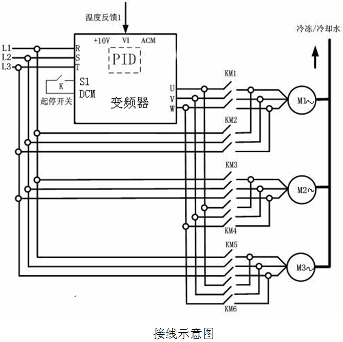
Note: in this scheme, Fuling DZB300 series general inverter is used, and the bypass of "municipal power" and "power saving" requires additional power distribution control cabinet and electrical accessories. One for use and two for standby or two for use and one for standby according to the actual situation
lParameter setting
F0.01=1 run command terminal control
F0.03=5 frequency command PID control
F0.05=48 run frequency upper limit
F0.06=15 run frequency lower limit
F0.10=2 reverse operation prohibit
F0.19=1 free parking
F1.20=1 square torque V/F curve
F2.01=1 forward running
F2.07=0 two wire control
F2.21=3 fault normally open output
F4.18=0 PID keypad given
F4.19=50 keypad preset OID setting
F4.20=0 PID analog channel VI feedback
F4.21=1 PID output is negative
F4.22=1 proportional gain
F4.23=0.1 integration time
F4.24=0.00 differential time
F4.25=0.10 sampling period
F4.26=5.0 PID control deviation limit
Actual equipment condition
lClosed loop control of refrigerant water pump system (detection of temperature difference between inlet and outlet)
The standard inlet and outlet water temperature of the central air conditioning system is 12 ℃ / 7 ℃, and the allowable temperature difference of the standard inlet and outlet water of the rated index condenser is 5 ℃. If the difference between the inlet and outlet water temperature is 2 ℃, so from the perspective of temperature difference, the actual demand for chilled circulating water is only 2 ℃ / 5 ℃ = 40% of the supply, in the case of variable frequency speed regulation, the actual speed of the pump can meet the requirements as long as it works at 40% of the rated speed, and the energy consumption of the pump is only less than 10% of the rated energy consumption. The insufficient exchange of energy causes the poor refrigeration effect of the system, so the energy saving space is very large. Under the condition of ensuring the supply of chilled water flow of the terminal equipment, determine the minimum working frequency of a chilled pump inverter (generally 25 Hz), set it as the lower limit frequency, lock the minimum working speed of the chilled water pump, and control the frequency increase and decrease control mode of the inverter by detecting the temperature difference between the inlet and outlet of the chilled water through the intelligent temperature controller, so that the frequency can not be increased when the chilled water return temperature is higher than the set temperature.
l Closed loop control of chilled water pump system in heating mode (detection of temperature difference between inlet and outlet water)
This mode is the same as the control scheme of the chilled water pump system when the heat pump is running (autumn and winter) in the central air conditioning.
lOpen loop control of cooling circulating water pump (detection of temperature difference between inlet and outlet)
The standard temperature difference between the inlet and outlet water of the central air conditioning system is 4 ℃ ~ 8 ℃, the standard temperature difference between the inlet and outlet water of the cooling tower is 3 ℃ ~ 5 ℃, and the temperature of the hot water used for heating is 50 ℃ / 60 ℃. This part is composed of cooling pump, cooling water tower and condenser. When the cooling water circulation system carries out indoor heat exchange, it takes a lot of heat energy away from the room, and the energy is transferred from the refrigerant in the main engine to the condenser, so that the temperature of the cooling water increases; The cooling pump will deliver the heated cooling water to the cooling water tower (outlet water) for energy exchange with the atmosphere, and then send it back to the condenser (return water) of the main engine after the cooling temperature is reduced. Therefore, the cooling water circulation system is affected by both outdoor environment temperature and indoor heat load, the water temperature on one side of the circulating water pipe can not accurately reflect the heat exchange capacity of the system. A temperature difference sensor should be installed on the main inlet and outlet pipes of the cooling pipe as shown in Figure 1. It is a reasonable energy-saving way to control the indoor temperature based on the temperature difference between the outlet water and the return water. When the external temperature is constant, the temperature difference is large, which indicates that the indoor heat load is large, so the speed of cooling pump should be increased and the circulating speed of cooling water should be increased; correspondingly, if the temperature difference is small, the speed of the cooling pump will be reduced, which will save about 5-10% energy compared with the single backwater temperature measurement. It is because of the excess effect of pressure and flow that the velocity of water flow and the temperature difference of heat exchange are smaller. Therefore, by reducing the total supply flow of the circulating water of the heat pump, it can be close to the reference value of the standard temperature difference, so as to achieve the purpose of energy saving.
Therefore, in the investigation of the actual operation conditions, it can not be simply judged according to the running current of the motor, if we simply look at the actual running current of the motor in the refrigerant circulating water system, there will be no much power saving space. Therefore, the basis should be based on the data of actual operating conditions: for example, the influence of factors such as capacity selection of system equipment, load change in different seasons and times, etc, in the actual operation of the central air conditioning system is basically not consistent with the standard indicators, most of the systems have small temperature difference, high head, flow rate and other phenomena. By using the technology of frequency control, the redundant flow and head of the system can be saved, so that the system can work under the best condition of energy consumption (when there is no redundant head and flow), so as to meet the system demand and minimize the energy consumption.
lCoil fan system control
One set of coil fan with motor of 0.40kw 220V is set in each room. The maximum temperature difference of coil fan is 10 ℃ ~ 15 ℃ (the temperature difference of general air inlet and outlet is 8 ℃). Coil fan system is a system that uses water and air as the heat transfer medium of indoor load, however, most of the main cooling and heating loads in the room are borne by the cooling medium water or heating medium water in the coil, the fan is mainly to meet the needs of the room for sanitation and ventilation, to improve the comfort of the room, only to bear part of the cooling or heating load.
The fan is changed from the original manual start and stop control fan through three speed control switch to frequency conversion control. After the transformation of VAV, the room temperature, especially in winter, can be stably controlled at 17 ℃± 1 ℃, compared with the power consumption of power frequency, its daily average energy saving is 80%, which is more than 60% of its rated power, especially the noise of the room after reconstruction has also been significantly improved.
lCooling tower fan control
Analysis of the current situation of the cooling tower fan system (generally two fans per set), the original control mode adopts the power frequency full speed operation under the direct start mode. Both cooling tower fans are running at full speed, the system lacks effective cooling effect detection, and fails to make full use of the opportunity of saving power under natural cooling state, resulting in two extreme states of cooling tower fans: either run at full speed or stop manually. Especially in spring, autumn and winter, because the manual operation can not respond to the change of cooling tower outlet water temperature in time to start and stop the fan, resulting in a great waste of energy in operation management. During the transformation, each set of cooling tower is operated with the inlet water temperature of 35 ℃ as the starting operation point of the fan, 30 ℃ as the stop operation point, and 35 ℃ ~ 30 ℃ as the basis for fan frequency regulation, and temperature PID variable air volume regulation is implemented. Through the actual operation test, the energy consumption under the VAV control mode is only about 40% of the power frequency start stop control mode, and the VAV control completely avoids the energy waste caused by the lack of real-time operation or imperfect management under the manual start stop power frequency operation mode. According to a large number of typical cases of energy-saving renovation of central air-conditioning system, the statistical data shows that after the successful energy-saving renovation of central air-conditioning system, the energy-saving rate of cooling tower fan system is more than 40%, and some cooling tower systems with large capacity cooling tower reservoir device can reach more than 50%.
lFeatures of frequency conversion energy saving system
◆The inverter interface is LED display, abundant monitoring parameters, simple keyboard layout and convenient operation
◆The temperature / temperature difference sensor is a digital double screen LED display, with convenient temperature parameter setting and easy monitoring
◆The inverter has a variety of electronic protection devices, such as over-current, overload, over pressure, overheating, etc., and has abundant fault alarm output functions, which can effectively protect the normal operation of the water supply system
◆After the installation of inverter, the motor has the function of soft start and stepless speed regulation, which can greatly reduce the mechanical wear of water pump and motor, and extend the service life of pipe group
◆The system realizes the PID closed-loop regulation of temperature, and the indoor temperature changes smoothly, which greatly improves the comfort
Conclusion
At present, the market of energy-saving technology transformation project of central air conditioning system is not only widely distributed, but also numerous, which lays a foundation for the application and promotion of energy-saving transformation in the market. According to statistics, at least 70% of the central air-conditioning systems that have been put into operation have not undergone any energy-saving transformation, and have good energy-saving space. The application of frequency conversion technology in central air conditioning system is of great significance to improve the automation level of central air conditioning, reduce energy consumption, reduce the impact on power grid, and extend the service life of machinery and pipe network.

Email: overseas@chinafuling.com